Posts

Preparation for Full Assembly and Production

Image
Following our presentation, there were a few issues that needed to be addressed. The drawings needed small alterations based on the materials we will be using. Spacing was changed slightly due to the sheet metal being in customary units rather than the metric we designed for (0.25 in vs 3 mm). Another change was moving the lower passive wheels down slightly as to accommodate the change in track sizing. With these changes, the designs are ready for other teams to incorporate their parts into the bogey. The files have been available for the last few weeks but now the track CAD is complete as well and ready for assembly.

Last Minute Details and Modifications

Image
After producing our shop drawings for the sheet metal components of the drive bogie, we were notified by the motor team that there was a clearance issue with the new track width. The in-hub motors would be overhanging by about 5 mm on each side. To rectify this, I have been planning out an adjustment to our CAD models to remove 10-12 mm of width on the drive bogie. Due to this being only a slight adjustment that doesn't affect all of our components, we are still moving forward on sourcing materials and preparing for production. We will be utilizing the central shop of the engineering department as well as the Makers' Space for fabrication. Below is one of the shop drawing that remains unchanged by our adjustments:

Heading into Shop Drawings and Fabrication

This week, we got the go-ahead from the guideway team to continue with our current designs. There were concerns that the loss of the wooden guideway would result in major changes to the guideway dimensions, and therefore the bogies. Thankfully, the guideway team has figured out how to utilize the old steel guideway with very similar dimensions to their designs. This means we can go ahead with our shop drawings and beginning ordering materials and fabrication. In addition, we have spoken with other teams to clarify our bogie designs and where their components will be integrated. The wayside power team will be designing an enclosure for their capacitors to be mounted to the slave bogie. We worked with the controls team to spec a set of linear actuators for our route selection assembly. The braking and steering team now has full control of the slave bogie to make their modifications.

Starting off the Spring

To begin the spring semester, we first had to adjust to the many changes that came from our new location for Superway. With the loss of the wooden full-scale track, there were worries that the designs would need major modifications to fit the older steel track. Fortunately, the guideway team has worked to ensure that the track design from last semester will remain mostly unchanged. This means that we can continue with little to no change from our past design. The next week will be spent reorganizing the file structure to make it easier to distinguish new from old files. Also, shop drawings will be made for the parts that must be manufactured.

Week 12: Bogie System Integration

This week was intended to do FEA on the drive bogie and work towards the finishing the modifications to the slave bogie. WE ran into some issues getting the model into ANSYS so the FEA we hoped for was not completed. We will keep working on this to get this important data. This week was mostly spent working with other teams on integrating their systems into the bogies. The Motor Team provided us with final sizing specs, allowing us to correct the mockup model we were using in our CAD assemblies. We also ironed out the spacing for the wheels relative to the tracks. Additionally, we are working on placing the route selection for Guideway Team. Finally, we have decided to use a simple pin system to link the two bogies. This will allow the motion we require for Maker Faire while giving the option of a linkage with more degrees of freedom when needed.

Week 11: Drive Bogie V4

Image
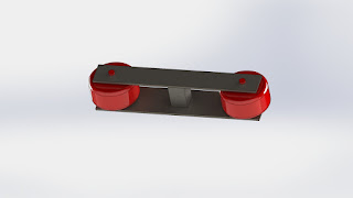
This week, I headed the redesign of the drive bogie. It was a huge relief that Wayside Power confirmed that they could power the two wheel drive system. That allowed me to simplify the designs and throw out the concepts I have for articulation of the wheels for turning. I took cues from Futran on their lower clamping wheel system, designing a rigid set of wheels that do not actively hug the bottom of the rail. These wheels aid in keeping the bogie on the tracks and prevent the drive wheels from losing traction with the rails. Additionally, the two sets of wheels are offset to prevent twisting on the rails. The passive wheel assembly This should mark the end of design for the drive bogie. From here, I will send off the CAD to my teammates for a full set of FEA tests. From there, I will alter the design as needed. I am confident in the design and feel that it may only require a few supports to be ready to build. Drive Bogie V4

Week 10: Presentation 2 and a New Design Direction

This week, we gave presentation #2 as an update on our project progress. Now that we have fully committed to a 2 bogie system, the design work has really picked up the pace. The drive bogie is through its preliminary stages and is ready for some finishing work before being sent off for FEA analysis. As CAD lead, I have taken on most of the design work for the drive bogie as it is being built from scratch. The goal was and continues to be looking towards the half-scale bogie as inspiration. The design used for the half-scale bogie is simplistic while having the potential to bear a large load. Due to our design relegating the majority of the load to the slave bogie, the drive bogie can be made of cheaper materials and have the design simplified even more. The slave bogie modifications are being taken on by my group members. The design will be based on the currently built bogie in the Superway warehouse. That bogie was created with the intention of bearing the load as well as providing ...