Posts

Week 12: Bogie System Integration

This week was intended to do FEA on the drive bogie and work towards the finishing the modifications to the slave bogie. WE ran into some issues getting the model into ANSYS so the FEA we hoped for was not completed. We will keep working on this to get this important data. This week was mostly spent working with other teams on integrating their systems into the bogies. The Motor Team provided us with final sizing specs, allowing us to correct the mockup model we were using in our CAD assemblies. We also ironed out the spacing for the wheels relative to the tracks. Additionally, we are working on placing the route selection for Guideway Team. Finally, we have decided to use a simple pin system to link the two bogies. This will allow the motion we require for Maker Faire while giving the option of a linkage with more degrees of freedom when needed.
Week 11: Drive Bogie V4

Image
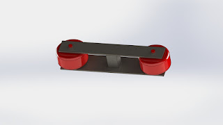
This week, I headed the redesign of the drive bogie. It was a huge relief that Wayside Power confirmed that they could power the two wheel drive system. That allowed me to simplify the designs and throw out the concepts I have for articulation of the wheels for turning. I took cues from Futran on their lower clamping wheel system, designing a rigid set of wheels that do not actively hug the bottom of the rail. These wheels aid in keeping the bogie on the tracks and prevent the drive wheels from losing traction with the rails. Additionally, the two sets of wheels are offset to prevent twisting on the rails. The passive wheel assembly This should mark the end of design for the drive bogie. From here, I will send off the CAD to my teammates for a full set of FEA tests. From there, I will alter the design as needed. I am confident in the design and feel that it may only require a few supports to be ready to build. Drive Bogie V4

Week 10: Presentation 2 and a New Design Direction

This week, we gave presentation #2 as an update on our project progress. Now that we have fully committed to a 2 bogie system, the design work has really picked up the pace. The drive bogie is through its preliminary stages and is ready for some finishing work before being sent off for FEA analysis. As CAD lead, I have taken on most of the design work for the drive bogie as it is being built from scratch. The goal was and continues to be looking towards the half-scale bogie as inspiration. The design used for the half-scale bogie is simplistic while having the potential to bear a large load. Due to our design relegating the majority of the load to the slave bogie, the drive bogie can be made of cheaper materials and have the design simplified even more. The slave bogie modifications are being taken on by my group members. The design will be based on the currently built bogie in the Superway warehouse. That bogie was created with the intention of bearing the load as well as providing ...

Week 9: Preparing for Presentation 2

This week, we began preparing for Presentation 2 which is scheduled for October 24th, 2018. This presentation is a chance for us to show how much progress we have made since Presentation 1. The major differences over presentation 1 for our group is a much clearer vision for our project. Prior to presentation 1, we were very recently introduced to the concept of a 2 bogie system. We knew almost instantly that this system would work better for the ideas we wished to implement. As Presentation 2 approaches, I can confidently say we are in a much more solid place with the project. We have a good understanding of Superway and the systems relevant to our project. In addition, we have a solid concept for our new drive bogie. The CAD for the initial version is nearly complete. From there, FEA will be performed and the model will be tweaked and prepared for prototyping.

Week 8: Drive Bogie V2

Image
This week was spent refining the drive bogie design to a more concrete idea. This version still requires a set of lower clamping wheels but represents a our vision for the drive bogie.  The Drive bogie is meant to be a small bogie with the sole purpose of propulsion. This bogie will be very lightweight and will not be load bearing. This bogie will allow the slave bogie to be more simplistic and used to carry more components. The next step for the coming weeks is to finish the drive bogie design and modify bogies from previous years for use as a slave bogie. From there, we will perform FEA to ensure the designs can handle their intended loads. Below is a picture of the current drive bogie iteration without wheels:

Week 7: Designing a Bogie

With the basic ideas laid out over the last few week, I began CAD modelling our drive bogie. Based closely on the Futran deployment in Africa, the drive bogie will not be load bearing and will serve solely as propulsion. This bogie will use the in-hub wheels supplied by the motor subteam. This bogie will contain all required components to to be fully independent and able to move while attached to a slave bogie or as its own unit.

Week 6: Presentation 1

This week, we gave out first major presentation. This was the first time of the groups outside of Full-Scale heard about our intention to change to the 2-bogie system. As such, there were quite a few questions regarding its advantages and how we planned to implement it. This week forward is where our work really begins. We are currently creating sketches of the bogies before getting a reference CAD model created.